The Beginning
After 70 years of flying model aircraft, I found that my reactions were slowing down, and I would have to find a new hobby. Model boats required a suitable pond for sailing, but a model railway layout could be built in the shed. A bit of internet research showed me how things had changed from the clockwork hornby set I had from the late 1930s to the early 1950s, and I resolved to set up an OO gauge DCC system and use Railmaster (at least for a start). This would give me scope for model building, electronics and computer programming.
The 0-6-0 locomotive supplied with the set ran quite well, but stumbled a bit over points. I learned from this that it was important for points to be flat on the table surface, so got rid of the "Trakmat". I also learnt to keep the rails clean using first an ink rubber, then a track cleaning carriage. The final solution was to fit a 1000 microfarad "stay alive" capacitor to the engine. This was the biggest which would fit in, but it turned out to be sufficient. This engine has since been converted to TSS sound (see page 3).
I then acquired a GWR King Class 4-6-0 locomotive with tender, "King George III", and fitted a Hornby R8109 DCC sound chip. This model has power pickups on the wheels of both the locomotive and the tender so had absolutely no problems with points, and did not need a capacitor to be fitted.
My collection has expanded as I picked up bargains from ebay.
The Transportable Layout
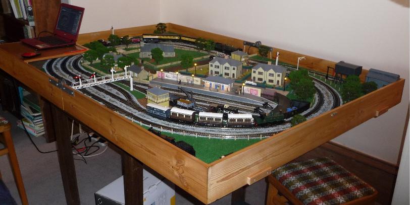
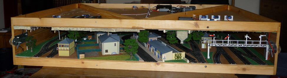
My layout measures 6ft x 4 ft, and folds into a 3ft x 4 ft package, which slips under a bed, or just fits in the back of my aging Toyota Corolla hatchback. This means I can take it to club meetings and similar events. While the small size is convenient, it does pose limitations in what can be represented, after all, it only represents a patch of land 150 yards long by 100 yards wide. The track layout is designed to give an outer oval for running express trains, an inner oval for local traffic and inside that is a loop with station and a goods yard. There are useful sidings off the outer loop.
The scenery, houses, trees, signal boxes and a level crossing are positioned so that they don't clash when the layout is folded,
It is fitted with two power supplies, 15 volts for the DCC, and 5 volts for driving everything else, such as lighting, motorising the level crossing, signals etc. The idea was to to limit the current that the E-Link unit would have to supply.
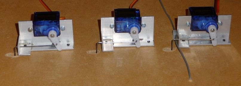
The turnouts are operated by the small SG90 servos available quite cheaply from Ebay. These are mounted under the deck and engage with the central hole in the points tie bar.
I designed very low cost dcc controllers using PIC 12F629
microprocessors to operate the turnouts. These are described in more detail on the next page.
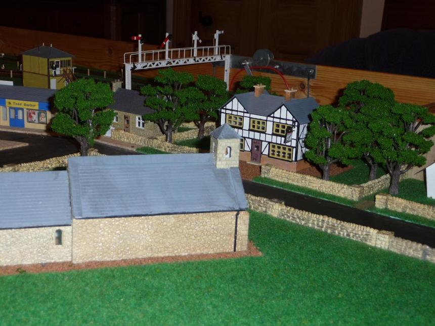
The signals are all scratch built from ABS, and are operated by servos under the deck. They are set automatically by the logical state of the points and level crossing. Surface mount LEDs form the lamps. Some of the buildings are Dapol kits, others are scratch built. Most of them have interior lighting.