Using a Servo to Operate Turnouts

  SG90 servos can be sourced very cheaply on Ebay, and cost considerably less than points motors.  A simple installation is shown below, where the servo is mounted below the layout board.

OO gauge Servo Operated Turnouts

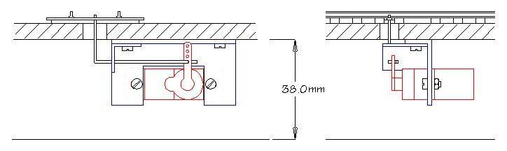
  The servo mounting bracket is fabricated from two pieces of aluminium angle, sourced from B & Q, which is screwed to the underside of the board.  The linkage is 20swg piano wire (about 2mm diameter)  which passes through a slot in the board and engages the centre hole in the tie bar.  The piano wire is sufficiently flexible to act as a spring to hold the closure rails in position.

  The throw of the servo must be set to provide just enough movement to position the point blades

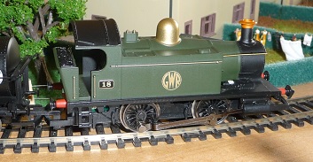
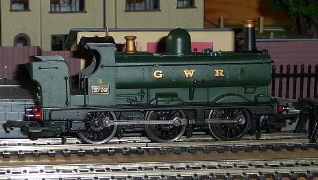
Fitting Sound to Hornby OO gauge  0-6-0 GWR 2721 Class


  Fitting sound to locomotives with tenders is relatively easy.  Recent models usually already have mountings for a speaker, and are fitted with an 8 pin dcc socket, so it becomes a "plug and play" exercise.

  Older models may have a dcc socket, but no provision for a speaker, so a plasticard mounting has to be fabricated.  Older still, and not dcc ready, require rewiring, fitting a socket, and speaker mounting..

  Models of tank engines provide more of a challenge .  Often there is not enough room for an 8 pin dcc socket, let alone a speaker inside, so some rearrangment of the insides in necessary.

  While the boxy shape of the 2721 class might appear to have room inside, the side tanks are filled with ballast weights, which are difficult to dislodge, and there is not much differece in room inside between this and Hornby's 0-4-0 models.

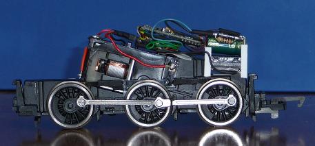
  However, there is just enough room to fit an NMRA 6 pin dcc socket and a sugarcube speaker, with enough space left for a 1000 microfarad "stay alive" capacitor, without having to modify the body shell or chassis.

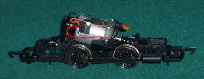
  The first step was to rewire the locomotive with a 6-pin dcc socket.  This is a bit fiddly, as the pin spacing is only 1.27mm.  The socket sits on top of the motor, as far back as it will comfortably go.

 The hornby sound decoders are fitted with 8 pin connectors, so this will also need changing.  (The socket can be purchased as   MULTICOMP PRO   MC-SVT1-S06-G  and the plug as  MULTICOMP PRO MC-HVT1-S06-G from CPC.

  Plugs and sockets with leads attached can be found on Ebay)

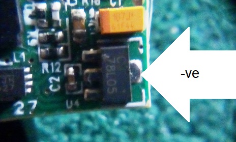
 The "stay alive" system requires a 0volt connection.  This needs another wire fitting to the circuit board.  The easiest place to connect is to the large pin on the 78L05 regulator chip, which is conveniently situated at the end of the board.

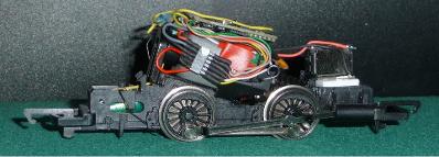
 I obtained a 15 x 11mm ESU sugarcube speaker kit from "Roads and Rails", which came with an ABS enclosure kit of 3 spacers and a back plate.  I opted for the thinnest installed package, with no spacers, and glued the back plate in position. ( It is very important to seal the backplate in position, otherwise you get very poor sound output.) The sound output from the tiny speaker is virtually the same as from the one supplied with the decoder board.

  I made a frame from 0.5mm plasticard to hold the speaker, facing downwards, leaving a 2 to 3mm gap between it and the loco chassis when it was installed.

DCC Sound on 0-6-0 Chassis

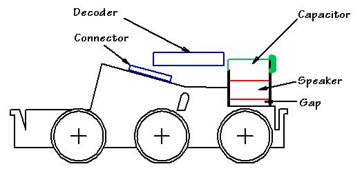
  The end plates are glued to the speaker frame and  the "Stay Alive" capacitor sits on the backplate of the speaker.
Small size is important for this component.  I obtained a Changxin 1000 microFarad 16V working, which measures 16mm long x 8mm diameter,  from Ebay. 

  If you have a steady hand, and a good soldering iron, this is not a difficult conversion.  The sugar cube speaker (if the backplate sealed well) gives ample volume, virtually indistinguishable from the original speaker.

Fitting Sound to Hornby Class 101

  This is harder than fitting sound to type 2721 as there is far less room inside. It is necessary to replace the ballast weight at the front of the chassis in order to make room for the speaker.  This is held in position  by some form of latex glue.  By inserting a craft knife plate between the weight and the chassis this can be loosened, and the weight removed.  A few pieces of lead in the ballast cavity will restore the balance of the model as lead is much denser than the material Hornby use.

  The Hornby DCC installation guide for "Smokey Joe", which uses the same 0-4-0 chassis, gives detailed instructions for fitting the basic DCC chip.  The TSS chips are larger, but can be fitted in the same way, but with the addition of a speaker.

  The Hornby guide shows a hard wired installation, but you may prefer to fit a 6 pin NMRA connector, which can be placed to one side of the motor.

  The speaker is mounted on a 2mm thick Plasticard packing at the front of the locomotive, over the ballast cavity. This may be glued in position with a dab of Copydex, so it is removeable. 
The packing is required to ensure the speaker does not foul the worm gear drive. The speaker is fitted with the smallest enclosure and can be glued onto the packing piece with polystyrene cement with the sealed side close to the boiler wall. Note that the speaker is set back 5mm from the front of the ballast cavity to clear the body shell, and its rear end lies between the body retainer clips.

  The cavity under the cab floor will just accommodate a 1000 microfarad "stay alive" capacitor, which I find necessary for 0-4-0 locomotives.
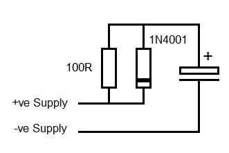
This is best fitted with a plug/socket connection so it can be disconnected when programming the decoder. (If fitted, a "Stay Alive" capacitor interferes with the "Acknowledge" signal which the decoder sends while being programmed.) Stay Alive capacitors are discussed below.

"Stay Alive" Capacitors

  Power is transferred from the rails to the motor through the wheels.  If the wheels lose contact, power is interrupted and the locomotive stops. The best way to keep locomotives running smoothly is the keep the track and wheels clean by wiping with a soft rag moistened with Methylated spirit.  Unfortunately, some gaps, such as at turnoffs are unavoidable.  Small locomotives (without tender mounted pickups) often stall or stumble as they pass over the plastic frog of the turnoff.  A "stay alive" capacitor stores power, which can fill in while contact is lost.

  The biggest effect of the loss in power is to cause the microprocessor in the decoder to "brown out", and have to reboot when power is restored.  The microprocessor then goes through its initialisation routines and restores the locomotive to its startup condition, ie zero speed, It remains in this state until its next packet is received from the controller. Larger locomotives, particularly those with tenders with power pickups have few problems, but small ones have a double whammy of needing a capacitor, but have little space to fit it.
  The "stay alive" circuit consists of the capacitor plus a diode and resistor.  The capacitor charges through the resistor, and supplies power when needed through the diode.  It is connected across the rectified  +ve and -ve lines in the decoder.

  Obviously, the larger (electrically that is) the capacitor, the better, but really all that is required is cover the short time period of loss of power.  I have found that 1000 microfarad (16V working) gives a really noticeable improvement, while obviously 4700 microfarad is better.  Larger than this is not really necessary, or even desireable. Fit the largest size which will go in the space available.

   The +ve line is the blue wire from the decoder, but a new connection to the decoder must be made for the -ve.  The easiest place to make a connection for the -ve line is the large tab on the 78L05 chip, conveniently placed at the end of the decoder board.

  The downsideof fitting a "stay alive" capacitor is that it interferes with reading CV values in Service Mode.  This is because it masks off the "acknowledge" signal which the decoder sends when replying to a query from the controller.
 "Acknowledge" consists of drawing power for a set length of time.  If this is supplied by the capacitor instead of the controller, the signal is not received and the reading process fails.

Consider connecting a "stay alive" by a connector, so it can be unplugged while the decoder is being programmed.


Make a free website with Yola