This page contains the electronic circuits and microprocessor source programs for a range of DIY DCC decoders
DIY DCC Accessory Decoder for Servos
DIY DCC Decoder for Switch functions
DIY DCC Decoder for Locomotives
DIY DCC Decoders
The Circuits and Software on this page are experimental in
nature and have only been tested with Hornby Railmaster.
Only limited testing has been carried out.
The circuits use various Microchip PIC microprocessors
The software is written in Microchip Assembler Language. A very good Editor/Assembler/Simulator program, MPLAB IDE, may be downloaded free from Microchip. Information and data sheets for the various microprocessors may be downloaded from the same site.
A Programmer is required to load the programs into the PIC microprocessor. This is not a difficult process, and suitable PIC Programmers can be sourced cheaply from Ebay.
Building DCC Accessory Controllers
Information about the DCC system can be found on the NMRA Web Site.
NMRA Standard section S-9.1 describes the technique for encoding data in the power supply to the track. Basically, the power is supplied as square wave ac, and then the data is represented by varying the width of the square waves. The data is sent in "packets" consisting of a "preamble" of a large number of "1"s to mark the start, followed by the address of whatever is being controlled, then by data which conveys the control information, and terminated by a validation byte, which enables a check to be made for a corrupted message.
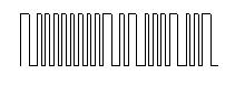
If the voltage present on the track was viewed on an oscilloscope, it would appear thus:
Longer waves represent a bit value binary ' 0 ' and shorter waves binary ' 1 '. The DCC controller continually sends out data packets to all the locomotives and accessories that have been registered.
Longer waves represent a bit value binary ' 0 ' and shorter waves binary ' 1 '. The DCC controller continually sends out data packets to all the locomotives and accessories that have been registered.
DCC Decoder designs using PIC Microprocessors
At the design stage for my model railway layout it was clear that a significant number of accessory decoders would be required, together with servo drivers. While little cost saving could be made from home built locomotive decoders, it was clear that a large cost saving could be made from designing my own accessory decoder units using PIC microprocessors. I have two versions, a minimum cost one which uses the minimum of components, and a “user friendly” one, which is slightly more expensive to construct.
Port Number = (Page Number -1) x 4 +Channel Number
This strange relationship come about because computer nerds think zero is a number, while the rest of us know it is just nothing. They count up: 0, 1, 2, 3, while the rest of us start at 1. This causes a number of apparent anomalies in the NMRA standards.
At the design stage for my model railway layout it was clear that a significant number of accessory decoders would be required, together with servo drivers. While little cost saving could be made from home built locomotive decoders, it was clear that a large cost saving could be made from designing my own accessory decoder units using PIC microprocessors. I have two versions, a minimum cost one which uses the minimum of components, and a “user friendly” one, which is slightly more expensive to construct.
Before describing these units, an explanation is necessary of the DCC addressing system. Most DCC documentation refers to “Port Numbers”, but in fact accessory decoders work from “Page Numbers”, each page containing four output ports. The locomotive “Port Number” system is in fact independent of the accessory numbering system, so it is perfectly safe to have a locomotive with the same port number as a turnoff (point).
The relationship between accessory port number, page number and channels numbered 1 to 4 is:
Port Number = (Page Number -1) x 4 +Channel Number
This strange relationship come about because computer nerds think zero is a number, while the rest of us know it is just nothing. They count up: 0, 1, 2, 3, while the rest of us start at 1. This causes a number of apparent anomalies in the NMRA standards.
My model railway layout has a separate 5 Volt supply to power servos, lights, level crossing motors etc to conserve the limited 15 Volt DCC power available from the E-Link unit. The cumulative current of these devices can add up quite significantly. LEDs typically draw 20ma each, while a single SG90 servo draws about10ma at idle, rising to 100-250ma when moving. When stalled, this rises to 350ma. (You have to plan for stalled servos.) Larger servos will draw more current. Remember, the Hornby power supply supplied with a Railmaster set is only rated at 1amp.
All the accessory decoder designs shown below require a 5 volt supply. (Obviously, the locomotive decoder does not.)
A Minimum Cost DCC Accessory Decoder for Servos
NMRA standard S-9.2.1 Section D defines the format of accessory decoder packets.
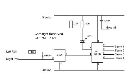
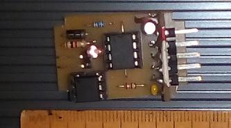
This design uses an 8 pin PIC12F629 microprocessor, which has a 4MHz instruction clock. It can be built for a cost as low as £3 depending on where you buy your components.
This DCC accessory decoder has four servo drive output channels. The CV1 page address and individual servo throws may be set when programming the microprocessor by changing the values in the EERAM. Alternatively, the page address can be set from the accessory decoder button on Railmaster in "Service Mode" using the setting for Hornby R8247, although the CV settings cannot be read back as an optocoupler is used to convert the dcc commands to 5 volt locic levels. So only the address can be set, anything else gets ignored.
The 15 volt DCC signal is converted to 5 volt logic level using a 4N35 optocoupler, which draws 15ma from the DCC supply. The PIC reads this and identifies the “1”s and “0”s of the transmitted packet. The decoder has a unique address and when this is identified in a packet, the data attached is used to determine the required servo output.
The servo throw is set in the firmware at 90 degrees, but can be altered by changing the values in the data memory. The output pulses to the servo, which are between 1000 and 2000 microseconds in length are sent for only 0.5 sec to reduce wear on the feedback potentiometer in the servo.
When you consider that the additional circuitry required for setting the servo throws will probably only be used once in the lifetime of the unit, I question whether it is worth the cost.
The assembler source code for the project can be downloaded HERE:
This DCC accessory decoder has four servo drive output channels. The CV1 page address and individual servo throws may be set when programming the microprocessor by changing the values in the EERAM. Alternatively, the page address can be set from the accessory decoder button on Railmaster in "Service Mode" using the setting for Hornby R8247, although the CV settings cannot be read back as an optocoupler is used to convert the dcc commands to 5 volt locic levels. So only the address can be set, anything else gets ignored.
The 15 volt DCC signal is converted to 5 volt logic level using a 4N35 optocoupler, which draws 15ma from the DCC supply. The PIC reads this and identifies the “1”s and “0”s of the transmitted packet. The decoder has a unique address and when this is identified in a packet, the data attached is used to determine the required servo output.
The servo throw is set in the firmware at 90 degrees, but can be altered by changing the values in the data memory. The output pulses to the servo, which are between 1000 and 2000 microseconds in length are sent for only 0.5 sec to reduce wear on the feedback potentiometer in the servo.
When you consider that the additional circuitry required for setting the servo throws will probably only be used once in the lifetime of the unit, I question whether it is worth the cost.
The assembler source code for the project can be downloaded HERE:
A User Friendly Accessory DCC Decoder for Servos
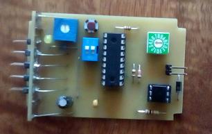
This DCC accessory decoder design allows the User to set the page address using a hex rotary switch. Since the DCC Standard does not have a page zero, the “0” position on the switch is interpreted as “16”, which gives 64 potential output port addresses. The limits for individual servos can be set, while in calibrate mode, using the potentiometer.
The design uses a PIC16F818 microprocessor, which has 16 I/O pins and an a/d converter, which is required for the servo setup system. It can be built for a cost as low as £6, depending on where you buy your components.
This circuit operates in much the same way as the previous one. Obviously, the program reads from the hex switch instead of EERAM to get the decoder page number, but the extra components in the circuit enable the throw settings of each servo to be adjusted in situa. The decoder can be physically installed, and then set up instead of needing to be connected to a programming track, etc.
The calibration mode is entered by first setting the potentiometer to the centre position and setting switch 1 to “ON”. This has the effect of disabling the DCC input, and enabling the input from the potentiometer.
The servo number to be calibrated is set on the hex switch (using positions 1 to 4). Switch 2 selects which extreme position (clockwise/anticlockwise) of the servo is being set.

When
the potentiometer is adjusted, the servo will change position. When it
is in the desired position, depressing the push button will save the
setting. The led will indicate when this is complete, and the button
can be released.
The assembler source code for the project can be downloaded HERE
Switch 2 can then be changed, and the other
extreme position can be set. Another servo can then be selected on the
hex switch, and so on.
To exit from the calibrate mode, reset the hex switch to the page setting, and turn off switch 1.The assembler source code for the project can be downloaded HERE
A DCC Accessory Decoder for Switch Functions
There are many situations wher a simple relay driver is needed to operate street or carriage lighting. This design operates as a four function accessory decoder, and so can be operated in the same way as for points.
Circuit "A" takes the power from the DCC system, and generates a 14 volt and 5 volt power line. The pic 12F629 microprocessor decodes the DCC signal and produces four logic level outputs corresponding to the 4 channels. The pic itself can only source or sink 25ma on any output pin, which is sufficient for one LED, or a relay with a 500 ohm 5 volt coil.
(It is far cheaper to use a transistor than a relay to switch higher currents, but then all current is being drawn from the DCC supply, while a relay can be used to switch a different (isolated) supply.)
Circuits "B" and "C" show the alternative additional circuitry for each of the pic output ports. The relay could be a SIL reed relay, most of which can switch up to 1 amp. The BC337 transistor is rated at 800ma.
The switcher can be set up in railmaster using the button switches as if it were a Hornby R8247. The normally on or normally off setting can be made using the "Left" or "Right" functions.
The attached program listing sets the port numbers at 5, 6, 7 and 8, but these may be changed, either by editing the listing, or by using the accessory
decoder button on Railmaster in "Service Mode" using the setting for Hornby R8247. The page number can be rewritten, but CV settings can not be read back.
If a switcher is installed in a carriage, a "Stay Alive" capacitor can be fitted to prevent the lights dipping as it rolls over points.
The assembler source code for the project may be downloaded HERE.
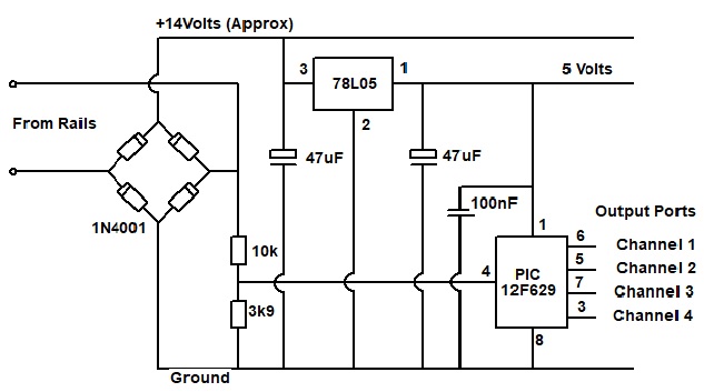
Circuit "A"
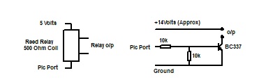
Circuit "B" Circuit "C"
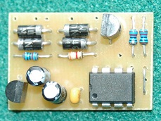
A single channel version with transistor switch
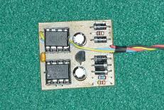
as installed in a carriage
A Simple Locomotive DCC Decoder using a PIC Microprocessor
This project was started during the Covid Lockdown when other activities stopped. The objective was to try to understand the NMRA DCC standards, and how they were implemented by Railmaster and not to design a state-of-the-art decoder. While the current design works quite well, it is inferior to some of the latest, commercial locomotive controllers.
The circuit was knocked up from components in my parts box, and is limited by having no provision for using feedback from back EMF. Whereas modern dcc speed controllers use a PID algorithm comparing the command signal with speed deduced from the back EMF of the motor, my circuit uses the speed step number to set the pulse width modulation ratio directly.
NMRA Standard S-9.2.1 sections A and C define the control packets, and Standard S-9.2.3 defines the Service Mode, which is used to programme the decoders.
The NMRA Standards are not straightforward, having been devised to include methods in use by various manufacturers before the standards were introduced. Thus there are different methods of encoding the address, different resolutions for speed control and different methods of writing CVs. I resorted to using an arduino based “sniffer” to find out how Hornby has interpreted the standards, and what Railmaster was actually transmitting to the rails.
A board can be built fairly cheaply which would fit in many of the locomotives without using surface
mount components. There is no real cost saving compared with the cheapest commercial decoders. The picture shows it on a Hornby 0-4-0 chassis. It just fits inside the body shell.
The 15 Volt AC from the rails is full-wave rectified, and a TO-92 size 78L05 provides the 5 Volts for the microprocessor.
The circuit uses an 8 pin PIC12F683 microprocessor to process the dcc data. This has an 8 MHz internal clock, and a Pulse Width Modulation module to drive the L9110H motor driver.
The data sheet for the L9110H chip does not provide a lot of information, but states that it is rated at 12 volts. However, it seems happy enough operating at the 14 volts output of the E-Link at the low currents involved. The data sheet provides no information about suitable PWM frequencies, but I found it was not happy much above 1 kHz.
The controller has to work in a very electrically noisy environment owing to poor pickup from the rails. There were many adjustments necessary between having a program which ran on the Microchip SIM simulator, to having one which ran smoothly in the locomotive.
All of the CV values can be read
by Railmaster using the Service Mode. If CV8 is read, the chip will
return the number 13, which is the NMRA code for Do-It-Yourself
manufacture. (See NMRA S-9.2.2 Appendix A). If Railmaster reads this,
it wants to know more about the decoder -- don't bother!
All CVs except CV7 and 8 can be changed by Railmaster. Writing any value to CV8 will cause all CVs to be reset to the original default values.
The decoder has been installed on a standard Hornby 0-4-0 chassis, and has had quite a few hours running time. It performs well and I will not be replacing it in my test loco in the near future. .As regards to the original objective, the project has proved very useful as a tool to explore the DCC control system.
The only points which could be seen as drawbacks are that a very low volume hum can be heard at low speeds owing to the low PWM frequency required for the L9110, and that no back EMF compensation has been included, so the loco has a jerk when starting from rest, and slows slightly under load on bends and inclines. But then so do locos fitted with certain other controllers.
The 15 Volt AC from the rails is full-wave rectified, and a TO-92 size 78L05 provides the 5 Volts for the microprocessor.
The circuit uses an 8 pin PIC12F683 microprocessor to process the dcc data. This has an 8 MHz internal clock, and a Pulse Width Modulation module to drive the L9110H motor driver.
The data sheet for the L9110H chip does not provide a lot of information, but states that it is rated at 12 volts. However, it seems happy enough operating at the 14 volts output of the E-Link at the low currents involved. The data sheet provides no information about suitable PWM frequencies, but I found it was not happy much above 1 kHz.
The current version of the program can
accept either a single or a two byte address, and 28 or 128 speed step
control.
Service Mode writing and verifying of CVs is implemented. CV values can
be read back by Railmaster using the CV bit manipulation direct addressing mode. As with most decoders, reading of CV values does not work if a "Stay Alive" capacitor is fitted, as this will prevent the "acknowledge" signal from working.
CV2
is implemented to set the pulse width necessary to start the motor.
Acceleration and deceleration using CV3 and CV4 are still under
development, (meaning when I get round to it).The Functions F1 ,F2, F3
are available as 5 volt logic signals on pins 2, 3 and 6 of the PIC
12F683.
All CVs except CV7 and 8 can be changed by Railmaster. Writing any value to CV8 will cause all CVs to be reset to the original default values.
The decoder has been installed on a standard Hornby 0-4-0 chassis, and has had quite a few hours running time. It performs well and I will not be replacing it in my test loco in the near future. .As regards to the original objective, the project has proved very useful as a tool to explore the DCC control system.
The only points which could be seen as drawbacks are that a very low volume hum can be heard at low speeds owing to the low PWM frequency required for the L9110, and that no back EMF compensation has been included, so the loco has a jerk when starting from rest, and slows slightly under load on bends and inclines. But then so do locos fitted with certain other controllers.

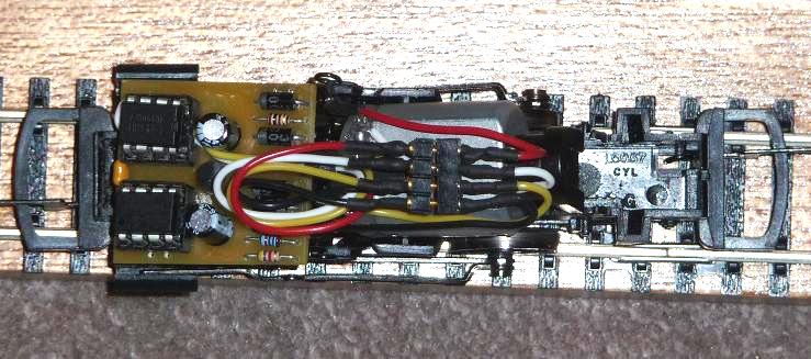
The board on a standard Hornby 0-4-0 chassis
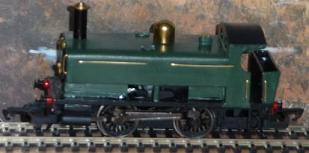
TheTest Locomotive
It should be noted that the NMRA standard specifies a track voltage of between 7 and 27 volts. While the L9110 chip seems to cope with the Railmaster output, it would probably not be suitable for use at the higher voltages.
The assembler source code for the project can be downloaded HERE:
As these circuits and programs are experimental in nature, I would appreciate any comments to klubsec@btinternet.com.
© Copyright GEERAIL